


Automotive Connectors, Terminals & Crimping: What Matters Most
Reliable electrical systems start with the right connector and terminal selection. From terminal retention and locking features to material compatibility and crimp quality, every detail influences the durability and performance of a wiring harness.
Understanding these fundamentals helps engineers and manufacturers improve system reliability, reduce maintenance, and ensure long-term performance. This guide outlines the key considerations when selecting automotive connectors and terminals.
What Are Automotive Connectors and Terminals?
Connectors vs Terminals: The Difference That Matters
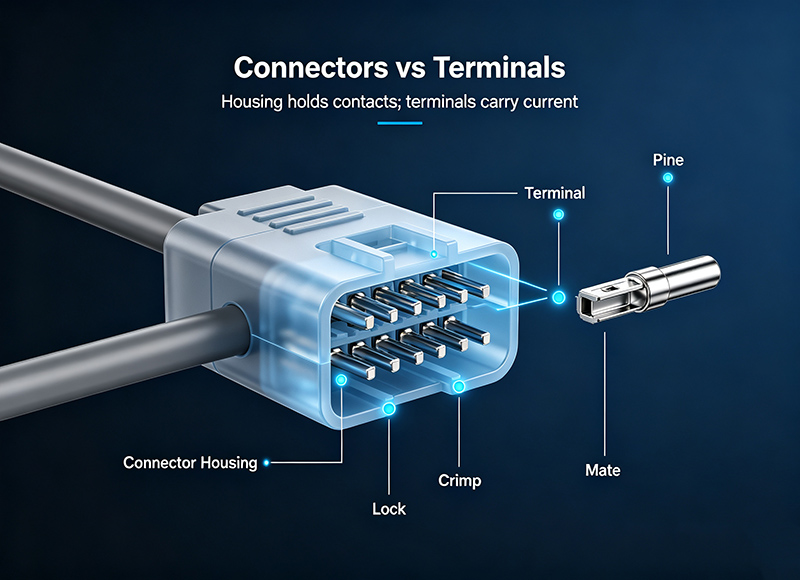
A connector is the plastic housing that holds multiple electrical contacts in a fixed position. It snaps into a mating connector to join two wiring harness sections together. A terminal is the metal contact inside that housing.
The terminal crimps onto the end of a wire and locks into the connector cavity. You can replace a damaged terminal without replacing the connector housing. You cannot replace a connector housing without removing every terminal inside it.
Types of Automotive Connectors and Terminals
Common Connector Types
Wire-to-wire connectors join two harness sections. A male housing with female terminals plugs into a female housing with male terminals. These dominate underhood applications where harness segments need to separate for engine removal. Wire-to-board connectors mount directly to a PCB inside an ECU or body control module.
Board-to-board connectors stack PCBs inside modules where space is tight, common in ADAS camera packages and infotainment head units. Sealed connectors use silicone grommets and interfacial seals to achieve IP67 or IP69K ratings.
Unsealed connectors live inside the passenger compartment where water ingress is not a concern. The cost difference between a sealed and unsealed 12-pin connector can exceed $1.50 per mated pair.
Common Terminal Types
Ring terminals bolt onto a stud and handle high current. You will find them on alternator output posts and battery distribution blocks. Spade terminals slide onto a flat blade and tolerate frequent disconnect cycles, common in instrument panel harnesses where the cluster gets removed during service.
Bullet connectors join a single wire pair with a cylindrical snap fit, used in low-current sensor circuits where the harness may need to separate for diagnostics. Pin terminals insert into a connector cavity and lock with a retention lance molded into the terminal itself.
The lance engagement force is the single number that determines whether a terminal stays seated or pushes out the back of the connector during harness installation.
How to Identify the Right Automotive Connector
You have a damaged connector on a 2019 model year vehicle in the service bay. There is no part number visible. Identifying the replacement starts with three visual checks.
Pin Count, Shape, and Color Codes
Count the cavities. Count them twice. A 12-pin connector and a 14-pin connector can look identical from two feet away and use the same manufacturer tooling. Note the connector body color. Toyota uses gray for certain engine bay connectors and black for interior. Bosch uses beige for many ECU connectors. The color narrows the search from thousands of possibilities to dozens.
Slots, Locks, and Brand-Specific Designs
Look for a manufacturer logo embossed on the housing. TE Connectivity stamps their logo on the connector body. Sumitomo uses a stylized S. Yazaki uses a Y inside a circle. The logo tells you whose terminal series fits inside. Measure the terminal pitch with calipers. A 2.54 mm pitch connector accepts different terminals than a 2.8 mm or 1.5 mm pitch connector even if both are 12-pin and gray.
Check the connector position assurance lock. CPA devices are red or yellow secondary locks that slide over the primary latch. If the replacement connector does not have a CPA and the original did, the harness will separate during thermal cycling.
Wire Crimping Standards and Quality
A bad crimp fails silently. The wire pulls out during a harness pull test at the assembly plant or six months later when engine vibration works the strands loose.
IPC, UL, and SAE Requirements Explained
IPC/WHMA-A-620 is the governing standard for wire harness assemblies in North America. It defines three classes.
- Class 1 covers general electronic products where the primary requirement is function.
- Class 2 covers dedicated service products where extended life matters, which is where most automotive harnesses land.
- Class 3 covers high performance products where continued operation is mandatory, applied to airbag clocksprings and ABS sensor harnesses.
SAE J1939 covers CAN bus termination practices for commercial vehicles. UL 486A covers terminal and connector requirements for safety circuits.
What Determines a Good Crimp
Strip the wire to the correct length. Too short and insulation gets crimped inside the terminal barrel, creating a high-resistance joint that passes a continuity test and fails under load. Too long and exposed conductor strands short to adjacent terminals inside the connector.
The crimp tool must match the terminal manufacturer’s specified die set. A generic pliers crimp deforms the terminal barrel asymmetrically, creating strands that fracture at different rates under vibration. Pull force testing per SAE AS7928 verifies the bond.
A 20 AWG wire in an open barrel crimp should withstand 50 newtons minimum before conductor separation. Cross-section analysis under a microscope confirms whether the crimp barrel compressed the strands into a cold-welded gas-tight bundle or just squeezed them together loosely.
Installing Automotive Connectors Step by Step
Wire Prep and Stripping
Cut the wire square with a clean blade. A diagonal cut smears copper strands and creates a ragged edge that snags during terminal insertion. Strip the insulation without nicking the conductor.
A single nicked strand reduces the effective cross-sectional area and creates a stress concentration point. Use a thermal stripper for PTFE and XLPE wire types common in high-temperature underhood applications. Mechanical blade strippers work for standard PVC insulation.
Crimping and Terminal Insertion
Crimp the terminal onto the stripped wire in a single motion. The terminal should capture both the conductor barrel and the insulation barrel. The conductor barrel deforms around bare copper to create the electrical connection.
The insulation barrel wraps around the wire jacket to provide strain relief. Insert the crimped terminal into the connector cavity until the retention lance clicks. Pull back gently on the wire. If the terminal moves, the lance did not engage. If it holds firm with less than 1 mm of movement, the terminal is seated.
Common Mistakes That Cause Field Failures
Incorrect strip length is the most frequent root cause of warranty connector failures. A strip too short leaves insulation under the conductor crimp. A strip too long leaves exposed conductor outside the terminal barrel where it can short to the adjacent cavity.
Poor crimp height control is second. Under-crimping leaves air gaps between strands. Over-crimping fractures individual copper strands and reduces the effective conductor count. A terminal that passes a pull test can still fail a microsection analysis. Both checks are required for process validation.
Your Automotive Connector Solutions
Choosing the right automotive connectors is not just about matching part numbers. It is about ensuring stable performance, long-term durability, and dependable protection across the entire wiring system.
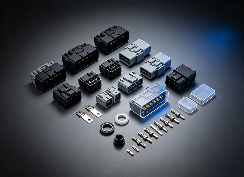
From connectors and terminals to seals, cavity plugs, caps, and covers, each component plays a role in keeping electrical connections secure in demanding automotive environments. LHE provides a wide range of automotive connector solutions, including connector caps and covers designed to protect exposed or unused ports from dust, moisture, corrosion, and damage.
Whether you need standard components or customized connector protection, LHE can help you find the right solution for your application.
Looking for reliable automotive connector solutions? Contact LHE to discuss your project requirements.
--- END ---
LATEST NEWS


